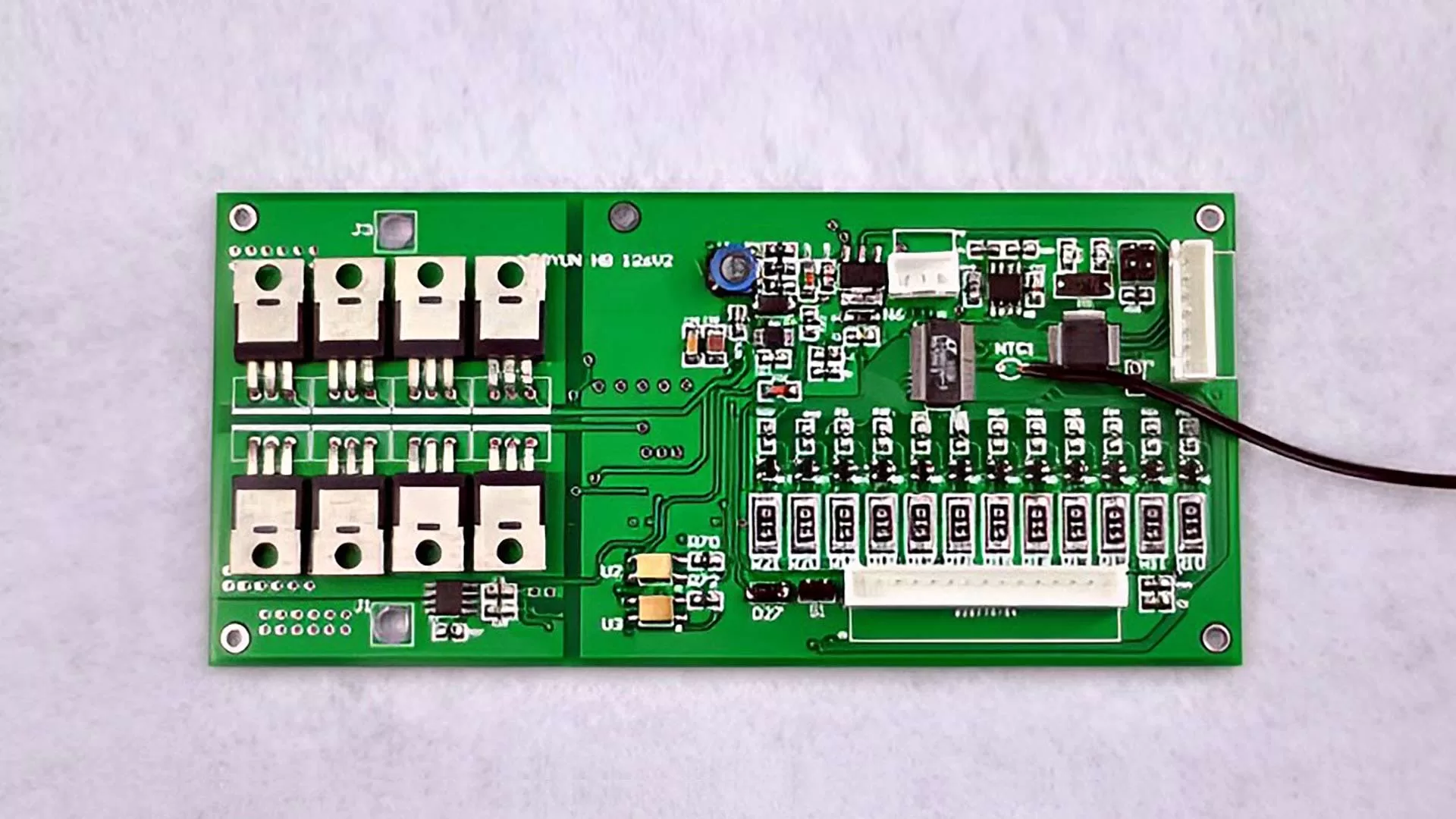
In a custom lithium battery pack, the communication protocol is defined by the BMS configuration and determines how the battery exchanges data with the outside system.
Different protocol choices lead to very different outcomes in data structure, response behavior, and system compatibility.
To address these differences, modern Smart BMS designs support multiple battery communication protocol options, each suited to specific application requirements.
Purpose of Battery Communication Protocol
Battery management system communication protocol is to achieve reliable data exchange, command transmission and real-time monitoring on voltage, current and temperature between the battery and external systems.
Data Transmission and Sharing
Battery communication protocol enables real-time data exchange between various modules within the BMS, monitoring key battery voltage, current, temperature, State of Charge, and State of Health.
Battery Thermal Management
Collaborative Control and Management. Battery communication protocol implements balancing management and work with thermal management within the battery pack, optimizing energy distribution and insulation monitoring systems.
Fault Diagnosis and Alarm
Battery communication protocol transmits battery real-time fault information, such as over-current, over-voltage,insulation faults. It supports fault location and diagnosis, shortening repair time.
System Integration and Compatibility
Battery communication protocol offers unified communication interface standard for equipment from different manufacturers, ensuring compatibility, interoperability and simplifying system integration.
Remote Monitoring and Maintenance
Battery communication protocol utilizes wireless communication technologies, such as Wi-Fi, Bluetooth, NB-IoT to support remote monitoring and real-time battery status monitoring.
Types of Battery Communication Protocols
Battery management system communication protocols are selected based on your specific application requirements rather than universal standard. Mastering various protocols information helps with selection.
RS232
RS232 is point-to-point, short-distance serial communication interface that supports 15–20 meters communication distance with a single connected device, featuring with low cost and simple structure. RS-232 supports full-duplex communication with independent transmit and receive channels in the physical layer. However, it is used in command–response manner and therefore behaves like half-duplex communication.

RS485
RS485 is serial and multi-point communication protocol that uses differential signal transmission, resisting electromagnetic interference for industrial conditions with electrical noise. It supports up to 1200 meters transmission distance and 10Mbps data transmission speed. It enables bidirectional and real-time communication, and can support up to 32 nodes.
RS485 protocol supports communication between multiple devices on the same bus and ideal for distributed and centralized monitor and control. However, data transmission speed decreases with increasing distance and number of nodes, and lack of unified standard.
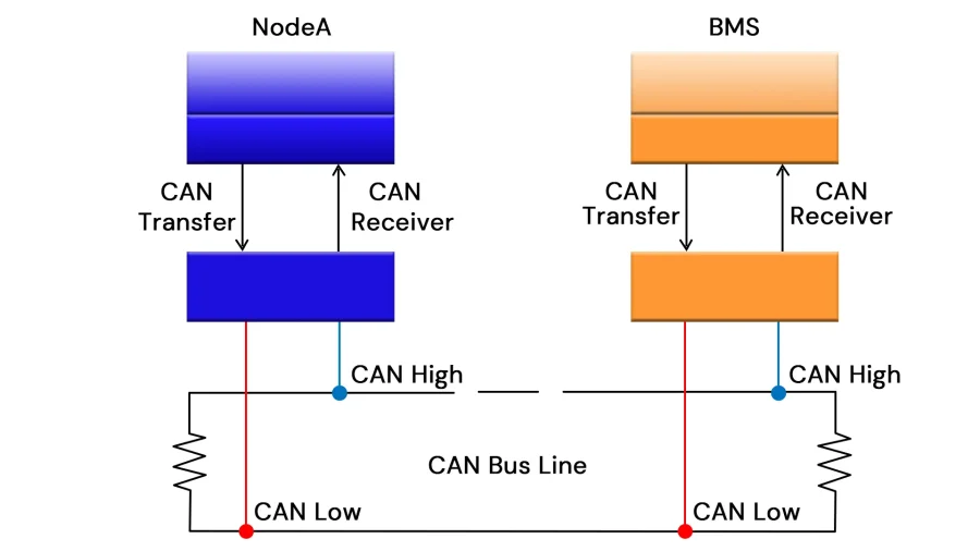
CAN (Controller Area Network)
CAN (Controller Area Network) is a serial and multi-node bus communication protocol designed to improve communication efficiency between electronic control units (ECUs) with specifications defined by the ISO11898 standards.
It offers strong noise immunity for safe communication between BMS and system controllers in real-time and supports multiple nodes on a shared bus. CAN bus length is limited to 10–40 meters at 1 Mbps, reducing the bit rate allows communication over hundreds of meters. The study indicates that the CAN protocol in battery management systems supports real-time monitoring and control. Its reliable communication mechanisms ensure synchronized data flow and coordinated control across battery modules, enhancing overall system performance (Zhang et al., 2025)
UART (Universal Asynchronous Receiver-Transmitter)
UART stands for Universal Asynchronous Transmitter module for serial communication with other devices. It supports flexible baud rates and data formats, enabling low-speed data transfer at short distances using low-power between BMS and external devices such as PCs, sensors, and display modules.
I2C
I2C (Inter-integrated Circuit) is a simple, bidirectional two-wire synchronous serial bus developed by Philips. Its speed varys by mode with 100 kbps at standard mode and 400 kbps at fast mode. The I2C bus supports short-distance communication between devices, requiring two bidirectional lines(SDA and SCL) for synchronous serial data transfer with moderate speed and complex programming.
Bluetooth Low Energy (BLE)
Bluetooth provides a low-power and short-distance wireless communication method for low power consumption and infrequent data transmission, enabling fast connection and data transfer. It is suitable for portable and mobile battery-powered devices.
Interactive Battery Communication Protocol Selector
Selecting the right battery communication protocol is critical for ensuring reliable data transmission in a battery management system (BMS). The interactive selector below helps engineers identify the most suitable communication protocol based on system environment, reliability requirements, and application type.
BMS Communication Protocol Selector
Expert tool for selecting the most suitable battery communication protocol based on environment, reliability, and system architecture.
| Technical Feature | Protocol Capability |
|---|---|
| Max Data Rate | Up to 1 Mbps |
| Network Topology | Multi-Master Bus |
| Fault Detection | CRC + Message Arbitration |
| Typical Applications | Electric vehicles, industrial BMS, robotics power systems |
Tips: While the selector provides quick recommendation, engineers should evaluate additional factors such as data rate requirements, communication distance, and system architecture. The following section explains considerations when selecting battery communication protocol.
How to Select Battery Communication Protocol?
When consider specific battery communication protocol for your devices, mastering their pros and cons are critical. Here we compare major communication protocols and their suitable for your applications.
Battery Communication Protocols Comparison
When selecting battery communication protocol for specific application, mastering the specifications like the distance, data rate, topology, and reliability is critical. Here we compare common battery communication protocol features and summarize their role in BMS.
| Communication Protocol | Distance | Speed | Topology | Typical Role in BMS |
| CAN (Controller Area Network) | 10–40 meters at 1Mbps; up to hundreds of meters at lower bit rates | Up to 1Mbps | Multi-master, Bus | Primary BMS communication. Module-to-master, vehicle systems |
| RS485 | 1200 meters at low speed(100 kbps) | Up to 10Mbps | Half-duplex, Bus | External BMS communication. Industrial energy storage monitoring |
| I2C (Inter-Integrated Circuit) | < 1 meter | 100 kbps at standard mode and 400 kbps at fast mode | Bus, Multi-drop | Internal IC-level communication (AFE, sensors) |
| RS232 | 15–20 meters | Up to 115kbps | Full-duplex, Point-to-point | Configuration, commissioning, diagnostics |
| UART | < 10 meters | Configurable ( < 1Mbps) | Point-to-point | Debugging, data logging, service interface |
| BLE(Bluetooth Low Energy) | Up to 100 meters | 1Mbps at Bluetooth 4.0 and 2Mbps at Bluetooth 5+ | Star, Wireless | Mobile monitoring |
Pros and Cons of Different Communication Protocols
While technical specifications define communication protocol function, BMS design also requires understanding their strengths, limitations, and use cases.
The table below summarizes the key advantages and constraints of common battery communication protocols to support selection.
| Communication Protocol | Type | Advantages | Limitations | Applications |
| CAN | System-level bus | High reliability, strong noise immunity, real-time communication | Limited bandwidth, short distance at high bit rates | BMS, Electric Brake System, Auto Start and Stop |
| RS485 | Industrial serial bus | Long-distance transmission, low cost, strong EMI resistance | No unified application layer and requires protocol design | Industrial energy storage, remote BMS monitoring |
| I2C | Board-level bus | Simple wiring, low power, multi-device addressing | Short distance, limited speed, bus loading constraints | AFE communication, sensor data acquisition inside BMS |
| RS232 | Point-to-point serial | Simple implementation | Poor noise immunity, limited distance and scalability | Temporary testing, calibration, firmware updates |
| UART | Point-to-point serial | Flexible baud rates, low hardware overhead, easy debugging | No multi-node support, limited distance | Service ports, data logging, configuration interfaces |
| BLE | Wireless interface | Cable-free, low power, convenient mobile access | Not suitable for real-time or safety-critical data | User interfaces, diagnostics, field maintenance |
Key Technical Factors Affecting Protocol Selection
Choosing the appropriate communication protocol depends on system architecture, operating environment, and performance requirements. Engineers consider these factors when select battery communication protocol:
- Device Quantity. RS232 is suited for single-device connections and simple structure systems. And RS485 and CAN are better for multi-nodes system due to their scalability .
- Transmission Distance. RS485 and CAN are the ideal for long-distance communication due to their robust transmission capabilities. I2C are efficient options for short-range communication, such as a single device or board
- Data Transfer Rate. CAN is ideal for real-time, high-speed data exchange required in automotive and industrial applications. I2C are suitable for low-speed data exchange in simpler, low power systems.
- Noise Immunity. Prioritize RS485 and CAN in electrically noisy environment, such as industrial environment and electric vehicles, where robust communication and fault tolerance are essential.
- Power Consumption. Low-power protocols like I2C and BLE to reduce energy consumption for portable battery-powered devices. CAN and RS485 consume more power but are vital for high-drained devices like robots, motors.
- Fault Detection. Choose protocols with error detection mechanisms, like CAN with CRC. RS485 and Modbus require external monitor while I2C and UART offer error check for less critical systems.
- Compliance and Standards. Ensure the protocol complies with industry standards, such as ISO26262, UL2580, IEC62619. This guarantees safety, reliability, and legal conformity for integration into regulated systems.
Architectural Choices in Battery Communication Design

Proprietary protocols and standard protocols are two types of battery pack communication protocols. Learn how to accelerate your custom battery pack development and design.
Proprietary VS. Standard Battery Communication Protocol
Proprietary Protocols (Non-Standardized Protocols) are defined by the device manufacturer and used for communication between specific brands and models of battery packs and their devices. These protocols feature with flexibility and specificity, which are unique and customized. However, they have compatibility issues, hindering interchangeability and system expansion. Applications include:
- Specific brand battery packs and chargers to ensure compatibility and safety.
- Industrial customized battery systems. Large-scale energy storage projects to meet high safety and special functions.
- Automotive manufacturers’ proprietary battery management system achieves battery performance optimization and fault diagnosis.
Standard battery communication protocols facilitate interoperability between devices from different manufacturers, reducing system integration costs and complexity, and promoting the application of battery packs, such as electric vehicles, energy storage systems, and industrial equipment. CAN, Modbus, SMBus, RS485 are common battery communication protocol.
Wired VS. Wireless Battery Communication Protocol
Battery communication protocol involves wired communication and wireless communication. Wired communication follow international standards such as ISO and IEC and is suitable for devices requiring stability, real-time performance, and large-scale centralized systems in electromagnetically environments. On the contrary, wireless communication, such as Bluetooth and Wi-Fi, offers advantages in flexibility, remote monitoring, and low-power applications.
Communication Rules and Message Structure
Unified communication format are vital to ensure the efficient data transmission between the Battery Management System (BMS) and other devices
This not only helps eliminate communication delays but also guarantees the integrity and reliability of the information. We introduce the battery communication protocol data transmission procedures, fault detection, addressing.
Message Structure and Communication Flow
Each message transmitted follows a fixed structure. For example, in the CAN protocol, the data frame includes a start bit, identifier, data, and CRC checksum. Each device transmits data in specific sequence as defined by the protocol, ensuring the message is sent and received in the correct order. Multiple devices can send data simultaneously, but conflict resolution mechanism ensures there are no collisions.
Communication Process
CAN uses multi-master bus architecture in which multiple nodes request bus access. Arbitration mechanisms ensure that only one message is transmitted at a time without data corruption.
BMS master control module periodically sends request frames, and the slave modules respond with data frames based on the request frame content, enabling battery parameter acquisition and status reporting.
Upon receiving data, the master control module verifies data integrity using CRC checksum. If the verification fails, it requests the data again.
Error Detection and Handling
The system monitors the bus status and triggers the error handling process upon detecting error frames, bit errors, and format errors to ensure. Retransmitting data, reducing the communication speed, and entering passive error mode are useful measures to ensure communication reliability.
Acknowledgment and Retransmission
The receiver sends an acknowledgment (ACK) message to confirm successful data receipt. If the sender does not receive the acknowledgment, it will retransmit the data. This mechanism ensures no data is lost, maintaining the reliability of communication.
Conclusion
Battery communication protocols define how a lithium battery pack interacts with chargers, controllers, and monitoring systems, making them a fundamental part of BMS configuration, not merely a data transmission layer. The protocol selected directly influences system compatibility, communication reliability, and long-term scalability.
By understanding the characteristics and trade-offs of different battery communication protocol options, project teams can make informed decisions that align with their system architecture and application requirements. In custom battery pack development, addressing communication protocol selection early in the BMS design phase helps reduce integration complexity, shorten development cycles, and improve overall system stability.
To learn more about how communication protocols are integrated into custom BMS architectures, explore our Custom Battery Management System (BMS) Design capabilities.