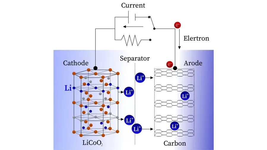
Li-ion batteries are widely used for different applications. The materials’ chemistry of li-ion can not withstand overcharge, over-discharge, overcurrent, short circuit, and ultra-high temperature. Lithium-ion batteries, especially custom lithium ion battery packs, need a BMS (Battery Management System) to ensure the battery is reliable and safe. The battery management system is the brain of the lithium battery and reports the status and health of the battery. Let’s get a better understanding from this article.
What is a BMS System?
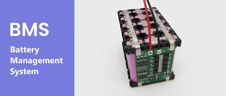
The BMS (Battery Management System) serves as the circuit protection component in the battery. It continuously monitors and regulates the voltage and current, ensuring optimal performance and safety.
The Main Component of Battery BMS:
- PCB There are three normal PCB board types, single board, double-sided board, and four-layer board.
- The best BMS for lithium batteries must adopt the famous brand ICs which decide the price and quality.
- Mosfet acts as a switch in the circuit. However, the on-resistance of the MOSFET affects the battery performance. High-quality Mosfet has smaller on-resistance, which causes the li-ion battery with a smaller on-resistance and stronger load. Besides, high-quality mosfet has few power consumption.
- NTC, gauging the side temperature of the Li-ion battery.
BMS Topology
Centralized BMS topology, distributed BMS topology and modular BMS topology are three major topology types. The topology of battery management system plays key role in determining how battery packs are monitored, controlled, and maintained.
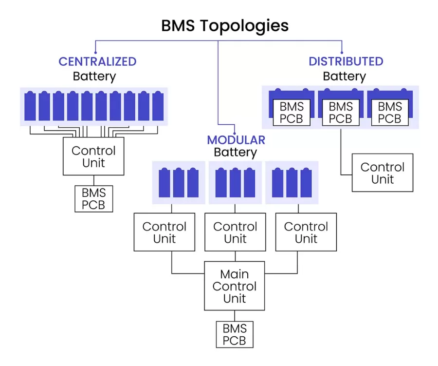
Centralized BMS Topology
In centralized BMS topology, a single BMS printed circuit board (PCB) contains a control unit that monitors all battery cells using multiple communication channels. This design leads to a larger, less flexible BMS. However, its cost-effectiveness and simplicity make it popular for lower-power applications such as electric bikes, IOT devices, and power tools.
Distributed BMS Topology
The distributed BMS architecture equips each battery module with an independent control board. All modules are connected to the central master controller through CAN to achieve data and command transmission.
The advantage of this architecture is high reliability. Each module have monitoring function, and the failure of a single module will not affect other modules. It has strong scalability and adjust the system size by adding and removing modules, making it suitable for electric vehicles, electric ships. However, its disadvantage is that it needs to manage multiple hardware units and communication networks, making system complex and costly.
Modular BMS Topology
In modular BMS topology, multiple slave control units are deployed on the module-level PCB, each monitoring voltage, temperature of specific battery module. These control units connect with main control unit through CAN, which is integrated into the master control PCB and is responsible for integrating data.
The modular BMS topology supports flexible expansion, but the communication control is more complex, making it an ideal choice for container energy storage. At the same time, its easy maintenance can make up for the increase in integration costs.
The following table shows the description, advantages and disadvantages, and applications of the three topologies:
| Topology | Description | Advantages | Disadvantages | Application |
| Centralized | Single control unit monitors and controls the whole battery pack | Simple, easy to implement | Less reliable, bulky wiring | power tools, intelligent robots, IOT smart home , electric forklifts, electric bicycles, electric golf carts. |
| Distributed | Each battery pack has its own BMS board | More reliable, scalable | More complex, expensive | Electric vehicles,Boat,etc. |
| Modular | Battery groups divided into modules with individual BMS | Flexible, scalable | More complex, require communication | Container energy storage system (EMS), energy storage power station. etc. |
Battery Balancing Technology
Battery balancing technology equalizes the state of charge (SOC) of all batteries in a multi-cell battery pack. This technology prolongs the life of the battery pack while ensuring safe operation. Passive balancing and active balancing are two common battery balancing methods.
Passive Battery Balancing
It also called energy-dissipative balancing, releases the excess power in high-capacity batteries by resistance heat release. When a cell reaches full charge before others during charging, this method dissipates excess energy through resistors to eliminate overcharging. Passive battery balance’s advantages include a simple circuit architecture and low cost. However, it suffers from low energy efficiency and puts more pressure on battery thermal management.
Active Battery Balancing
It is known as called energy-transfer balancing. Battery active balance is more flexible. When charging, active balancing transfers excess power to low-capacity battery. When discharging, it transfers excess power to high-capacity battery. Compared with passive balancing, active balancing is more efficient in energy utilization, but the circuit design cost will also increase.
Battery Thermal Management System
Battery thermal management systems (BTMS) play a vital role in maintaining optimal operating temperature range of batteries, especially in electric vehicles. It ensures battery safety, efficiency and service life. These systems are part of the battery management system (BMS) and are designed to control the cooling and heating of the battery pack. The main operation process includes:
1.Temperature Monitoring
Multiple temperature sensors are deployed within the battery pack to monitor battery temperature in real-time. These sensors transmit the collected temperature data to the Battery Management Unit (BMU).
2.Data Processing and Control
BMU receives the temperature data and performs analysis and processing. It formulates thermal management strategy based on battery temperature, charge and discharge status.
3.Implementation of Thermal Management Strategy
- Air Cooling Strategy: CAN transmits high temperature data from the BMU to the BMS, which actives air cooling devices like fans to increase airflow and dissipate heat. Cooling efficiency is optimized by controlling fan speed and designing air ducts.
- Liquid Cooling Strategy: A circulating coolant absorbs heat via cold plates attached to battery modules. The heated coolant then transfers heat to the outside through radiators. Coolant flow rate is adjusted based on real-time battery temperature monitoring.
- Thermal Isolation and Equalization: Thermal insulation materials are used to isolate heat among modules, preventing thermal runaway caused by heat transfer. Thermal balancing technology can minimize temperature difference between cells, ensuring uniform temperature distribution across the whole battery pack.
4.Warning and Protection
If the battery temperature exceeds the safety range, the BMS issues a warning signal to alert the engineer. In extreme cases, the BMS activates emergency protection mode, such as disabling battery charging/discharging functions.
How Does A BMS Work?
Activate the BMS
When the BMS P+ and P- have no output in the protection state. You can activate the BMS by short-circuiting B+ and B-.Dout and Cout will be at a low level (the two ports of the protection are high-level protection). The state supports the switches open.
Charge
P+ and P- are connected to the positive and negative poles of the charger. The charging current passes through the MOS to charge the battery. The VDD and VSS of the protection IC are the power supply terminal and the cell voltage detection terminal. The voltage of the battery cell continues to increase. When it rises to the protection voltage of the battery cell (overcharge protection voltage), at this time COUT will output a high level to turn off the corresponding MOS switch, and the charging circuit will also be turned off. , after overcharge protection, the cell voltage will drop. When it drops to the IC voltage threshold (overcharge protection recovery voltage), Cout returns to a low-level state and turns on the MOS tube.
Discharge
The IC’s VDD and VSS also detect the battery voltage when the battery is discharged. When the cell voltage drops to the IC threshold (over-discharge protection voltage), Dout randomly outputs a high level to turn off the corresponding MOS transistor. The discharge circuit is disconnected. After over-discharge protection, the cell voltage will rise. When it rises to the threshold voltage (over-discharge protection recovery voltage), Dout returns to a low level to turn on the MOS switch.
Overcurrent & short-circuit
When the discharge current becomes too large, the internal resistance of the MOSFET (in saturated conduction) causes a voltage drop across its terminals—from B- to P-. The protection IC monitors this voltage via the V- and VSS pins through resistor R2. Once the voltage reaches the overcurrent detection threshold (typically 0.15V), the IC triggers a response: Dout outputs a high signal, turning off the MOSFET and immediately disconnecting the discharge circuit to prevent damage.
NTC Work Process
The battery operates without overshoot, overcurrent, and overdischarge. However, the temperature of the battery rises due to long operating hours, and the NTC is placed close to the battery cell to monitor the battery temperature. As the temperature rises, the resistance of the NTC will increase. When the resistance drops to the set value, the CPU will issue a shutdown command to stop charging the battery, thereby protecting the battery.
A BMS has the protection of overcharge, discharge, short circuit, and temperature protection.
The Difference Between Smart Battery Management System and Hardware Battery Management System
The technology of hardware BMS is more stable than smart battery management systems. The software engineer codes the hardware BMS which manages or monitors the battery pack status. The BMS is the brain of the lithium-ion battery. We not only are good at designing and developing the BMS but also inspecting the risks. The battery management system manages the Li-ion battery performance. The smart BMS has the UART, I2C, CANBUS,rs232, and rs485 communication protocols. The smart BMS has more safe and smarter than the hardware BMS.
CMB engineering team always pursues reliable and excellent performance on Li-ion rechargeable battery packs and BMS.
The Main Functions of the Battery Management System
Overcharge protection
Overcharge protection means that during the charging process of lithium batteries, as the voltage rises beyond the reasonable range, it will bring uncertain dangers. The overcharge protection function of the protection board is to monitor the voltage of the battery pack in real time. When it is charged to the top of the safe voltage range, it will cut off the power supply to prevent the voltage from continuing to rise, thereby playing a protective role.
When charging, the protection board will monitor the voltage of each string of the battery pack in real-time, as long as one of the strings reaches the overcharge protection value (the default charging voltage is 3.75V±0.05V), the protection board will cut off the power supply, and the entire set of lithium batteries will stop charging.
Over-discharge protection
Over-discharge protection means that during the discharge process of lithium batteries, as the voltage drops, if all the electricity is fully discharged, the chemical materials inside the lithium battery will lose their activity, resulting in failure to charge or a decrease in capacity. The over-discharge protection function of the protection board is to monitor the voltage of the battery pack in real time. When the battery voltage is discharged to the lowest point, it will cut off the power supply to prevent the voltage from continuing to drop, thus playing a protective role.
When discharging, the protection board will monitor the voltage of each string of the battery pack in real-time, as long as one of the strings reaches the over-discharge protection value (the default over-discharge voltage of ternary is 2.7V±0.1V, and the default over-discharge voltage of iron-lithium is 2.2V V±0.1V), the protection board will cut off the power supply, and the entire set of lithium batteries will stop discharging.
Overcurrent Protection
Overcurrent protection means that when the lithium battery supplies power to the load, the current will change with the change in voltage and power. When the current is large, it is easy to burn out the protection board, battery, or equipment. The overcurrent protection function of the protection board is to monitor the current of the battery pack in real-time during the charging and discharging process. The overcurrent protection circuit cuts off the current flow when the current exceeds the safe range to protect the battery or equipment from damage.
When charging and discharging, the protection board will monitor the current of the battery pack in real time. Once the set over-current protection value is reached, the protection board will cut off the power supply, and the entire lithium battery will stop charging and discharging.
Short Circuit Protection
A short circuit is formed when the positive and negative terminals of a battery are directly connected without any load. A short circuit can cause damage to the battery and devices.
When the lithium battery accidentally causes a short circuit (such as wrong wiring, wrong wiring, water ingress, etc.), the protection board will cut off the flow of current in a very short time (0.00025 seconds), thus playing a role in Protective effects.
Temperature Protection
Temperature control protection: The temperature control probe of the hardware protection board is welded to the main board inside the protection board and cannot be plugged. The temperature control probe can monitor the temperature change of the battery pack or the working environment in real time. The battery pack’s temperature control protection system will disconnect the charging and discharging when the temperature exceeds the set value (default: charging -20~55°C, discharging -40~75°C ). The system will reconnect the charging and discharging when the temperature returns to a reasonable range.
Balance Protection
Passive equalization means that when there is a voltage inconsistency between the battery strings, the protection board will adjust the voltage of each string to be consistent during the charging process.
When the protection board detects a voltage difference between the lithium battery strings. The protection board discharges (consumes) about 30-35mA from the high-voltage strings through the balance resistor when charging, when the number of high-voltage strings reaches the equilibrium value(LiNiCoMnO2: 4.13V, LiFePO4: 3.525V), and the other low-voltage strings continue to charge until full.
The battery BMS is the heart of the battery pack. The battery management system(BMS) reports the battery status and performance of the lithium-ion battery pack. It is obvious, clearly confirming the electronic request to match the BMS solution to the lithium-ion battery. CMB LAB, our battery management system design offers comprehensive monitoring for custom lithium-ion battery packs, which includes cell voltage tracking, cell balancing, and detailed health status readings via app and PC.
If you’re looking to integrate a tailored BMS into your next project, explore our customized battery pack development process.