Robotic battery packs handle two types of load at the same time. They supply short, high-current bursts for motion systems. These bursts occur during acceleration, climbing, carrying weight, and frequent start-stop cycles. They also provide a steady background current for computer and sensor systems. Both generate heat inside the battery pack.
The battery, motors, and processors share one confined chassis. As a result, the battery’s temperature depends on the whole robot’s thermal design. If the battery pack temperature is outside the cell operating range, peak power, runtime, and safety will worsen.
Quick Answer
The purpose of choosing robot battery thermal management is to keep cell temperatures within the charge and discharge range. This considers conduction, insulation, heating, and BMS (Battery Management System) control.
When a cell gets too hot or too cold, the BMS limits charge or discharge current. It blocks charging below the minimum charge temperature. In cold conditions, it preheats the pack before charging. Start by checking passive conduction and temperature-based current limits.
Add preheating for cold use. Add active cooling only when duty cycle, charging needs, enclosure limits, or ambient heat exceed passive control.
Key Takeaways
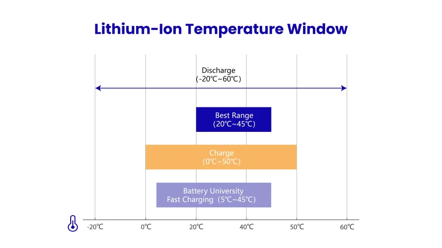
- The first important factor is to set a temperature range for charging. Most lithium-ion cells cannot charge below about 0°C. Review literature puts the best operating range around 20–45°C. For robots working in a cold environment, there may be a need for heating the battery prior to charging.
- Current magnitude, duration, and duty cycle set the heat. Heat follows P = I²R. Use RMS current for the heat budget, and check peak current separately for voltage sag and local hot spots. In addition, busbars, welds, connectors, and BMS switches add heat of their own.
- Passive starting is fine, and the pack only needs to accommodate the load. Low voltage, compact packs predominantly use conduction to manage heat, with BMS derating for managing excess temperatures. By contrast, active cooling suits sustained high power or hot environments.
- It is important to keep the cells within the pack at a uniform temperature. Maintain a temperature variation between cells of no more than approximately 5°C; the temperature of the hottest group of cells will determine the life of your pack.
- Provide actual load-based validation. Suppliers should be able to provide temperature-rise curves and resistance curves corresponding to the supplied test conditions, not just rated equipment specifications.
What is the Importance of Thermal Management in Robots?
Mobile robots, like AMRs, AGVs, and inspection robots, pack compute boards, motor drives, motors, and batteries into one body. Heat that dissipates too slowly stresses all of them at once. Among these, the battery is the most sensitive to temperature changes, and the consequences are the most severe. Temperature affects its usable capacity, charging, lifespan, and safety.
Three heat sources surround the battery, and they transfer heat to one another.
- Electronic Components: Controllers, drivers, and sensors are prone to failure because of environmental factors and their own heat generation. The Review notes that the maximum junction temperature for commercial components is typically 70–200°C. For equipment needing long service life and low maintenance, the average junction temperature should stay below 60°C.
- Motors: Friction, copper losses, and iron losses make motors generate heat. Too much heat can shorten insulation life, reduce efficiency, and cause demagnetization.
- Batteries: The Review states the best operating range is 20–45°C. It also limits temperature differences in the battery pack to 5°C. In a case study cited in the Review, a robot in a cold, high-altitude region used PTC heating. It also used an aluminum plate to equalize temperatures. This helped the discharge capacity at −20°C reach 93% of the capacity at 20°C.
All three live in one chassis. Consequently, heat from the drives and the computing board conducts into the adjacent battery pack.
Battery thermal design must therefore be part of the system-level thermal path, not an afterthought. When thermal design fails at the system level, the consequences cascade. For how cell-level overheating develops into pack-level failure, see our article on lithium battery thermal runaway.
What Temperature Does to Lithium-Ion Cells?
- Cold discharge: Impedance rises as temperature falls. This reduces available capacity. It also causes a deeper voltage sag. This makes under-voltage protection easier to trigger.
- Cold charging: At low temperature and high current, lithium deposits on the anode surface in metallic form instead of intercalating. This phenomenon is lithium plating. This increases internal resistance and, in severe cases, leads to the formation of dendrites, posing a risk of short circuits. Research indicates that lithium plating is the primary aging mechanism in low-temperature cycling. Per Battery University’s BU-410 guidelines, fast charging works between 5–45°C. Reduce current below 5°C, and do not charge below freezing.
- High Temperature: The SEI film keeps growing and uses up lithium. This reduces capacity and limits battery life and safety. Many chargers also stop charging above 50°C.
- Thermal Runaway: Thermal runaway is a process in which rising temperatures accelerate reactions, and the exothermic nature of these reactions further increases the temperature. UL notes that during this phase, the cell’s heat generation rate reaches several times its heat dissipation rate. Internal short circuits, overcharging, and extreme temperature environments can all trigger thermal runaway; see CMB’s article on thermal runaway for a breakdown of its three stages.
- Uneven temperature: NREL notes that poorly designed thermal management can create a large cell-to-cell spread, which affects each cell’s cycle life and can lead to warranty issues (NREL).
These problems land directly on operations. For example, packs that cannot charge in the cold or age early in the heat mean lost shifts, earlier replacements, and warranty risk. Note that the temperature bands above are illustrative only.
Always apply the cell and pack manufacturer’s limits, including any temperature-dependent current restrictions.
Where Does Heat Come From in a Robot Battery Pack?
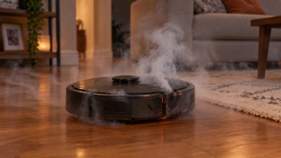
From three heat sources inside the cells: Joule heat, polarization heat, and reversible entropic heat. It also includes resistive losses in busbars, welds, connectors, and BMS switches. Heat can also come from nearby motors, processors, and the environment.
Joule heating follows a simple rule: heating power equals resistance times current squared, P = I²R. Battery internal resistance is that resistance, so at fixed resistance, doubling current quadruples heat. At high current, Joule and polarization heat dominate, and reversible entropic heat is much smaller.
The table shows heat per 10mΩ of total pack DC resistance. Substitute your own measured resistance.
| Current | Heat per 10mΩ |
| 5A | 0.25W |
| 10A | 1W |
| 20A | 4W |
| 40A | 16W |
| 100A | 100W |
A 100A burst lasting a few tens of milliseconds generates very little total heat but can cause a voltage drop; moderate continuous current generates heat slowly but accumulates over time. For the relationship between current capacity and C-rate, see “The Role of C-Rate in Battery Pack Design.”
Two of these differences matter more than the rest for cold-weather performance. First, sodium-ion cells can use aluminum current collectors on both the cathode and the anode, because sodium doesn’t form the same alloying reaction with aluminum that lithium does at low voltage.
How Temperature and Aging Change Internal Resistance
Lithium precipitation caused by charging at low temperatures increases internal resistance. Studies have also found that increased internal resistance significantly raises the heat generation rate. As internal resistance rises from low temperatures and aging, the same operation makes more heat. This creates a vicious cycle.
Heat Sources Outside the Cells
Busbars, solder joints, connectors, and the MOSFETs in the BMS have low thermal capacity. They heat up faster than the cells. This makes them prone to becoming hotspots. You can reference connector ratings based on the type of battery connector.
The central cells within the battery pack have longer heat dissipation paths and higher temperatures; in parallel branches, branches with higher temperatures have lower internal resistance and greater current shunting, which exacerbates temperature unevenness. NREL points out that thermal management must not only keep cells within the ideal temperature range but also minimize temperature differences between cells, as both factors affect battery life.
Robot Battery Cooling, Insulation, and Heating Methods Compared
Methods fall into passive (conduction, spreading, insulation, phase change), active (air, liquid, heaters) and BMS control. Before comparing hardware, first map your application to the evaluation priority:
| Application condition | Evaluate first | Data you must have |
|---|---|---|
| Indoor, low-to-moderate heat load | Conduction to the chassis + BMS derating | Temperature rise under the real motion profile |
| Sealed, IP-rated enclosure | Whether conduction through the enclosure is enough | Internal temperatures with the enclosure closed |
| Cold storage or outdoor cold start | Insulation + preheat + charge inhibit | Preheat time and energy from cold-soak |
| High utilization, frequent recharging | Thermal load of discharge and charge combined | Combined duty-cycle temperature rise |
| Sustained high power or hot climate | Forced air vs. liquid cooling | Heat load, space, weight, parasitic power, maintenance |
Thermal protection structures serve three purposes: insulation to keep external heat out or retain heat in cold conditions. They also provide conduction paths to the chassis. They also act as spreaders for uniformity. The trade-off is that insulation also traps the pack’s own heat.
Fixed designs also struggle when a robot moves between hot and cold environments. In the review, a nuclear-disaster robot needed 20–30 minutes to move from a normal zone to a hot one. Running in hot-zone mode at normal temperature also wastes efficiency.
| Method | How it works | Fit for battery packs | Main cost |
| Thermal pads / TIM | Lowers cell-to-enclosure interface resistance | Baseline for most packs | Weight, assembly |
| Graphite sheets, spreaders | Spread heat sideways | Packs with large temperature spread | Cost, thickness |
| Heat pipes | Phase-change transfer; micro heat pipes can be under 2mm in diameter | Tight spaces, hot spots | Complexity, cost |
| Phase-change material | Absorbs heat as it melts. Review example: a cold-storage inspection robot used PCM release on solidification plus vacuum insulation tiles to keep its battery above 0°C at −20°C, with 40% higher discharge capacity | Short thermal spikes, cold retention | Weight, low conductivity |
| Aerogel / vacuum insulation | Blocks heat flow. Aerogel is about 0.015 W/(m·K) at room temperature; vacuum panels reach 0.0015 | Shielding external heat, cold retention | Traps internal heat too |
| Forced air | Fans move air, roughly 5–10× natural cooling | Unsealed designs | Conflicts with ingress protection |
| Cold plate / liquid | Coolant carries heat away. Microchannel plates reach 0.02°C/W, but that is for high-TDP chips | Sustained high power only | Weight, leak risk, plumbing |
| Film or PTC heater | Preheats cells | Cold operation | Energy use, BMS control |
| Thermoelectric | ±0.5°C control, 10–50W cooling, COP only 0.267–0.618 | Generally not suited | Low efficiency, short life |
| BMS derating | Limits current near temperature limits | Essential | Some power loss |
Controlling heat at the source starts with load analysis. The BMS watches temperature and current and cuts current or stops charging near limits. Better still, it coordinates with the robot controller to reduce motion power.
The review describes a temperature-aware operation model that predicts system temperature 20 minutes ahead to within 4°C, and machine-learning-based adaptive cooling that cut energy use by 25%–30% with ±3°C control accuracy.
Designing Robot Battery Thermal Management – Five Steps
- Define the boundaries. This involves gathering information about the motion profiles of current usage (including peak current, duration of peak current, duty cycle), the range of ambient temperatures in the environment where the robot will operate, any adjacent components that will generate heat, and the charge/discharge temperature windows for the battery cells.
- Estimate the budget. The general formula for generating heat is Irms^2 * R, where Irms is the root-mean-square current drawn from the battery and R is the internal resistance of the battery. If the system is to maintain its operating temperature, the temperature rise within the battery will be approximately equal to the heat generated within the battery times the thermal resistance between the battery and its surrounding environment. The peak current is used to assess the possibility of hot spots and voltage sag within the battery cells.
- Create an appropriate heat route for the system. Heat path: Cells, Interface, Spreader, Enclosure, Chassis, Ambient. Isolate the pack from motors and treat the busbars and connectors separately. For cold conditions, reverse the logic: insulate and add a heater on the outside of the pack.
- Configure the settings for sensing as well as controlling.position sensors appropriately in the temperature-extreme regions, close to the sources of heat from outside, and on the board of the BMS. use warn, derate, and stop tiers, and block charging when the temperature is below the set value, and preheat the battery before charging, and also share status with the robot.
- Validation happens prior to creating any prototypes of the CFD and FEA designs. Screen designs with simulation before prototypes. Thermal-fluid analysis predicts pack temperature distribution and cuts prototype iterations. The final proof, however, is still a test under the real motion profile.
BMS Temperature Protection and Robot Controller Integration
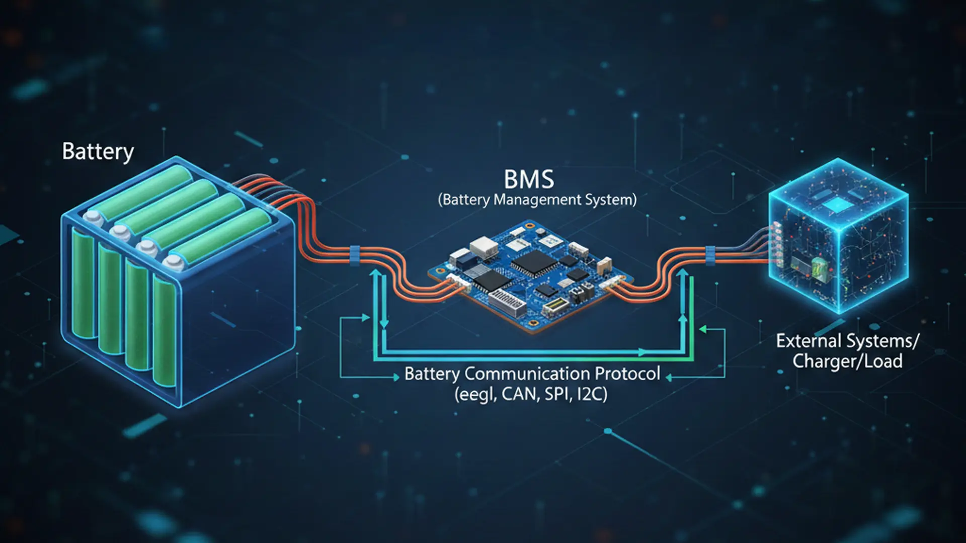
The BMS acts as the safety net for the whole thermal design. It monitors cell temperature and current, limits or stops charge and discharge at defined thresholds, and inhibits charging below the minimum charge temperature. It also controls the preheat heater.
A well-integrated system goes further. The pack reports temperature, current, and limits to the robot controller over RS485 or a similar bus. The robot can then reduce motion power early, instead of waiting for the pack to protect itself.
Review literature describes temperature-aware models that predict system temperature ahead of time, plus machine-learning-based adaptive cooling that cuts cooling energy. All of these build on the same principle: share the battery’s thermal state with the whole robot.
For a full treatment of monitoring, balancing, and protection, see the complete guide to battery management systems.
Application Example: CMB 25.2V 50Ah Robot Battery Pack
This example shows how to read thermal design boundaries from a battery pack specification. The CMB 7S10P 25.2V 50Ah battery pack uses 70 INR21700 5000mAh cells in a 7S10P layout—nominal 25.2V, 50Ah, about 1.26 kWh in roughly 6.7 kg.
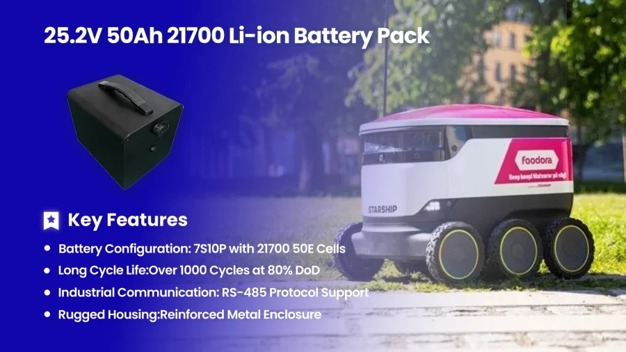
Its product specification sets the thermal boundaries: charging from 0 to 50°C and discharging from −20 to 60°C. Between −20°C and 0°C the pack can discharge but not charge, so a cold-weather robot needs a preheat step in its control strategy.
Standard current is 10 A (0.2C), maximum discharge is 20 A (0.4C), and burst discharge reaches 100±10 A for up to 100 ms. By P = I²R, every 10 mΩ of pack DC resistance dissipates about 4 W at 20 A, while a 100 ms burst adds little heat and mainly affects voltage.
Note that the specification lists initial AC resistance (1 kHz, ≤100 mΩ); for heat budgets, use measured DC resistance under your actual duty cycle. An RS485 interface lets the pack share data with the robot controller, so battery limits feed into whole-robot power and thermal management.
| Item | Specification |
| Configuration | 7S10P, 70 × INR21700 5000mAh |
| Nominal voltage / capacity | 25.2V (3.6V per cell) / 50Ah at 0.2C |
| Charge current | 10A standard, 20A max |
| Discharge current | 10A standard, 20A max, 100±10A burst (≤100ms) |
| Cut-off voltage | 18.9V (2.7V per cell) |
| Operating temperature | Charge 0–50°C; discharge −20–60°C |
| Weight / interface | About 6.7kg / RS485 |
| Cycle life | ≥1000 cycles to 80% retention, tested at 25±5°C with 0.2C charge/discharge per the specification |
To turn these boundaries into a validated thermal design, thermal-fluid analysis can model the pack’s temperature distribution under your robot’s actual motion profile. This step happens before any prototype exists.
Does your robot’s load profile or temperature range differ from this example? Send it to CMB engineers, and we can review your thermal budget.
How to Measure and Validate Robot Battery Thermal Performance
Use temperature rise, cell-to-cell difference, thermal resistance and temperature response time, recorded with full test conditions under a real motion profile.
| Metric | What it tells you |
| Pack temperature rise | Peak and steady temperature versus ambient |
| Cell-to-cell ΔT | Uniformity and current-sharing risk |
| Thermal resistance (°C/W) | Whether the heat path meets the budget |
| Temperature response time | How fast temperature and the BMS react to load or heater changes |
| Derating events and recovery | How much thermal limits cost your duty cycle |
The review also gives two common efficiency metrics: coefficient of performance (COP) for active cooling, ranging 0.21–2.32, and performance effectiveness for passive systems, ranging 0.1–0.98.
Test method: replicate the motion profile, measure at multiple points with thermocouples and thermal imaging, test cold discharge, preheated charging and hot ambient, and repeat after cycling because resistance rises with age.
Record ambient temperature, current, sensor locations and enclosure state. CMB’s approach is on its reliability test page.
When you request supplier data, ask for specific items. These include cell resistance versus temperature, plus pack resistance at room and cold temperature. Also request temperature-rise curves under sustained and peak current, with test conditions stated.
Further items include multi-point temperature spread, BMS thresholds, low-temperature charge inhibit, heater strategy, and connector ratings. Finally, ask for vibration and shock reports, along with cycle-life test conditions.
Challenges and Trends in Robot Battery Thermal Management
Today’s hard problems cluster in three places: the space-and-weight trade-off, fixed thermal designs that cannot follow hot-to-cold environment changes, and ambient heat traveling through drivetrain parts into the chassis.
The trend is for packs to open their temperature data to the whole robot, moving from passive current limiting to predictive coordination, while materials get lighter and more integrated.
Four Challenges for Custom Battery Packs
- Space versus weight:every gram of insulation or cooling material cuts payload and runtime, and insulation also traps the pack’s own heat, creating the insulation-versus-dissipation conflict. Passive options such as phase-change material are limited by how much heat they can store, which falls short for long shifts.
- Fixed designs cannot follow environment swings:robots often move between normal and extreme temperatures. In the review, a nuclear-disaster robot needed 20–30 minutes to enter a hot zone and 40–60 minutes for the round trip, and running in hot-zone mode at normal temperature (for example, phase-change material absorbing heat the whole time) lowers control efficiency and limits working time. For a pack, insulation that is useless at room temperature becomes a burden in the heat.
- Ambient heat travels through drivetrain parts:wheels, tracks and joints cannot be fully insulated and carry outside heat toward the interior, so the battery bay should avoid those heat paths and be isolated from drivetrain parts.
- Material strength versus weight:most insulation is mechanically weak and needs extra supporting structure, adding weight and complexity, and it must stay reliable under vibration and shock.
In selection terms, confirm three things with a custom pack supplier:
whether the pack offers a communication interface for temperature and limits, whether the thermal design can adapt to your operating environment (preheat and tiered derating, for instance), and whether the weight of insulation or cooling material is already counted in runtime.
FAQs
Why Do Robot Batteries Need Thermal Management?
Temperature controls capacity, charging permission, lifespan and safety, and a compact chassis traps heat. Thermal management keeps cells inside their safe window.
Why Can’t a Robot Battery Be Charged in the Cold Weather?
Below about 0°C, lithium can plate on the anode, causing permanent capacity loss and short-circuit risk. Most cells specify a minimum charge temperature, so check the datasheet.
Do Robot Batteries Need Liquid Cooling?
Usually not. Compact, low-voltage packs typically use conduction, heaters and BMS derating. Liquid cooling suits sustained high power, at a cost in weight and leak risk.
How Does a BMS Protect a Robot Battery From Heat?
It monitors cell temperature and current, limits or stops charge and discharge at thresholds, blocks cold charging, and reports status to the robot controller.
How Should a Robot Battery Heating System Work?
A film or PTC heater warms cells above the minimum charge temperature before charging. The BMS controls it and stops heating once the window is reached.
How Do I Choose a BMS for a Robot Battery Pack?
Start with the cell chemistry and pack configuration. Then check three capabilities: temperature-based current limits, low-temperature charge inhibit, and a communication bus such as RS485 or CAN. These features let the robot controller see the limits before the pack protects itself.
What Happens to Battery Temperature During Long Shifts?
Short bursts add little heat, but sustained operation accumulates it over hours. Therefore, size the thermal budget around RMS current and the full duty cycle, not the peak spec. In addition, watch derating events during testing, because they show how much the thermal design costs your duty cycle.
Is Constant Opportunity Charging Bad for Robot Batteries?
Frequent charge-discharge cycling at the dock stresses cells and adds heat from charging losses. However, a proper BMS makes it manageable. It blocks charging outside the temperature window and tapers current near the limits. For fleet robots, plan the charge schedule around cell temperature, not just state of charge.
Can Battery Swapping Replace Thermal Management?
No. Swapping extends runtime, but each pack still needs its own BMS and safe temperature window. Moreover, the dock then charges packs continuously, so dock-side thermal design matters too. In other words, swapping changes where the heat appears, not whether you manage it.