Lithium iron phosphate (LiFePO4) battery packs are widely recognized for their excellent thermal and structural stability, but the LiFePO4 short circuit is still a problem to be solved in LiFePO4 battery pack manufacturers. Despite their reputation for safety, there exists a potential for short circuits within LiFePO4 battery packs. This blog delves into the analysis of LiFePO4 short circuits, exploring the underlying causes.
What Are the Potential Causes of LiFePO4 Short Circuits?
The short circuit in a lithium iron phosphate battery pack can be caused by a single factor or the interaction of multiple factors.
What Is the “Micro Short Circuit” in the LiFePO4 Battery?
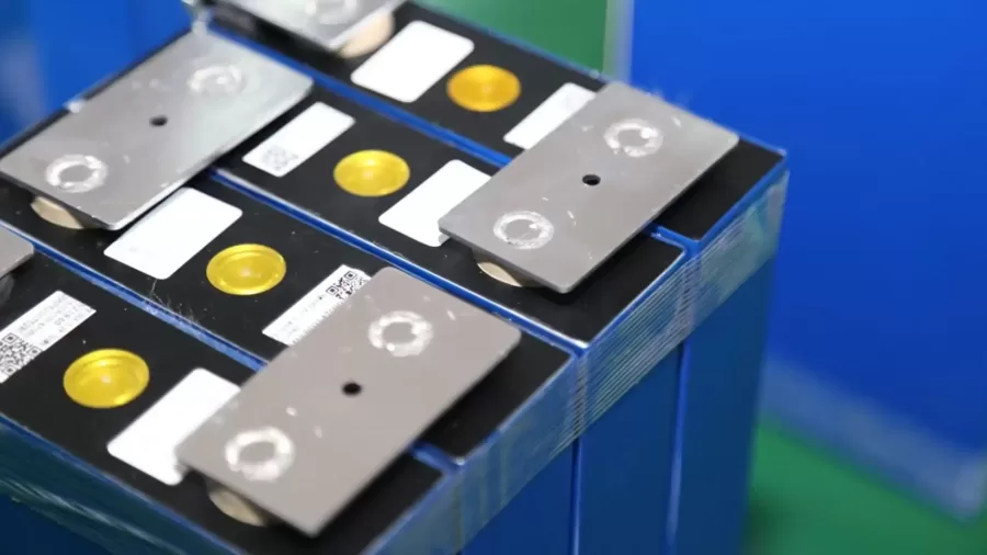
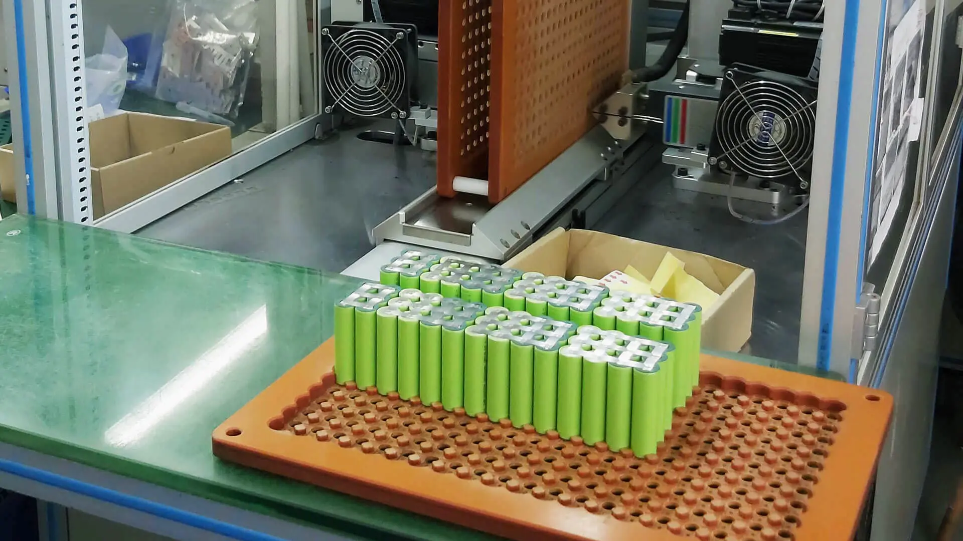
A short circuit of a LiFePO4 battery refers to a situation where the separator between the positive and negative electrodes is compromised, either due to dust particles piercing it or low-quality separator materials leading to reduced surface area or damage. It causes an abnormal connection between the positive and negative terminals of the battery through a conductor, causing a micro-short circuit within the individual cell. This is the micro-short circuit.
A battery pack is composed of LiFePO4 cells connecting in series or parallel. When a lifepo4 cell surfer a micro-short circuit, it continuously consumes energy during charge & discharge, even during storage. Proceed to the next step, it affects the overall performance of the battery pack.
How to Judge the “Micro Short Circuit” of the Battery?
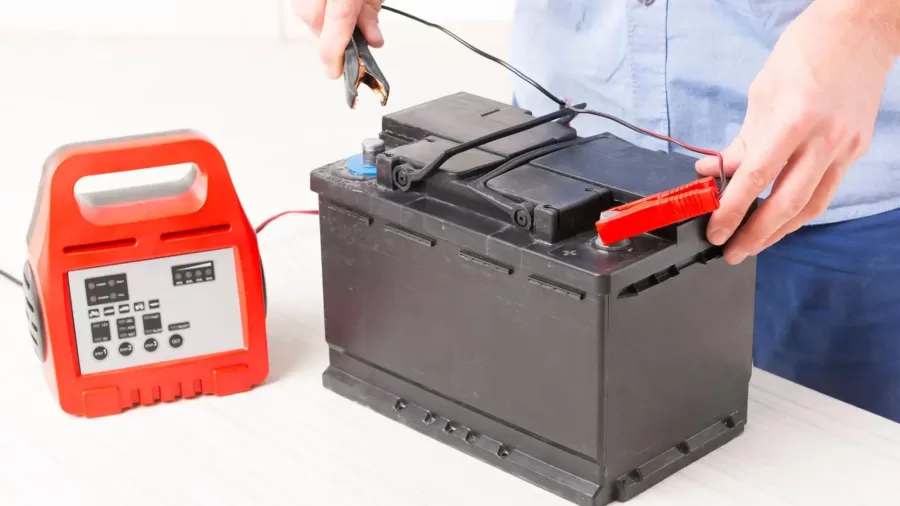
Charging slow-CMB’s laboratory found that when a micro-short circuit occurs in one of the cells in the battery pack, the battery pack can still charge and discharge normally, because the micro-short circuit caused imbalances within the battery pack and affected its overall performance, so compared to the lifepo4 battery pack without any issues, the battery pack with a micro-short circuit will charge slowly.
Lithium batteries in the long-term use of the aging process, the micro-short circuit is one of the aging characteristics, that can not be detected promptly and will lead to internal short-circuit, and the deterioration of the internal short-circuit situation is usually accompanied by an increase in the rate of self-discharge and heat, which leads to thermal runaway, triggering a safety accident.
Although the micro-short circuit will inevitably lead to the slow charging of the battery pack, the slow charging of the battery pack is not necessarily due to the micro-short circuit, because there are many reasons for the slow charging of the battery pack.
How to reduce the risk of micro short circuits in your battery pack? CMB is a professional LiFePO4 battery pack manufacturer, that can provide you with professional battery pack solutions to reduce micro short circuits.
Testing for Micro-Short Circuit of LiFePO4 Battery Cells
Indeed, ensuring the safety of lithium batteries is paramount, and various international safety standards include simulated test methods to evaluate internal short circuits. Here are some common test methods designed to simulate internal short circuits in lithium batteries:
- Plate Extrusion Method
The extrusion test is a common method to simulate internal micro-short circuits, and it is included in the majority of battery safety standards. However, there are significant differences in the methods of extrusion, such as flat plate extrusion and cylindrical extrusion. The latest IEC62660-2:2010 standard incorporates the advantages of various methods like flat plate extrusion, cylindrical extrusion, needle puncture, heavy impact, and metallic landfill to create a comprehensive test method. In the revision process of China’s GJB2374A standard, considering that some batteries cannot undergo extrusion using the flat plate method or that the cylindrical extrusion method lacks clear criteria for the occurrence of micro-short circuits, multiple options of flat plate and cylindrical extrusion are provided based on the actual battery conditions. The sudden voltage change in the battery is considered an indicator of the occurrence of micro-short circuit phenomena, which is generally reasonable.
- Needle Puncture
The needle puncture test involves inserting a metal needle into the battery, directly causing a short circuit between the positive and negative terminals. This test is too aggressive and does not effectively simulate internal micro-short circuit situations. Typically, intense internal short circuits are discovered during the manufacturing process. The needle puncture test method was used in the 1995 version of the American UL1642 standard but has been removed in subsequent versions. The upcoming UL2580 standard may adopt a milder blunt needle puncture to simulate internal micro-short circuits, which is closer to real-world micro-short circuit scenarios.
- Gunshot
The gunshot test involves placing the battery at a distance greater than 25 meters and shooting it with a firearm to create an internal short circuit. This method was developed for the GJB2374, a special standard in China, and is not typically included in general standards.
- Heavy Impact
The heavy impact test is a method that simulates internal short circuits by placing a metal rod above the battery and using a heavy object to strike the metal rod. This causes deformation of the battery casing and creates an internal short circuit. Similar to the extrusion method, this approach also presents an imbalance issue where batteries with thin casings may be disadvantaged. However, batteries with thinner casings tend to be safer in the event of an internal short circuit.
- Metallic landfill Method
Japan’s JIS standards and the NASA standards in the United States utilize the metallic landfill method by pre-inserting small metal pieces into individual battery cells to puncture the separator. This method examines the safety of lithium batteries under internal short-circuit conditions directly. However, this method carries significant risks, and it is preferable to employ robotic operations.
The test methods are aimed at evaluating the safety performance and response of batteries by simulating various short-circuit situations they may encounter. These tests are designed to ensure that lithium batteries remain safe under a variety of stresses and accidents and that serious accidents such as thermal runaway, fire, or explosion can be prevented.
Controlling Hazards Methods of LiFePO4 Short Circuit
Prevention of internal micro-short circuit hazards in lithium batteries must be addressed through various aspects, including individual lifepo4 cell design, material selection, and environmental process control. Additionally, to minimize the impact of internal short circuits in individual LiFePO4 cells and prevent chain reactions, some instructions must be followed in the design of custom lithium ion battery packs:
- Individual lifepo4 cell overheating isolation process
The individual lifepo4 cell overheating isolation process makes the battery pack charge/forced discharge lose efficacy when an internal short circuit or external impact occurs. It also prevents high temperatures, flames, and explosions of the failed individual cell from causing adjacent individual cells to undergo chain reactions, thus serving as a blocking mechanism.
- Individual lifepo4 cell connections
The detachment or poor soldering of electrical connections (such as wires, nickel straps, and fixed screws) between individual cells in the battery pack can result in high local resistance, causing high temperatures in the detachment area and leading to internal short circuits in nearby individual cells.
- Minimizing the energy of individual lifepo4 cells
The larger the energy of an individual lifepo4 cell and the fewer the number of lifepo4 cells in series and parallel make the custom lifepo4 battery more reliable. However, if the energy of an individual cell is too large, the damage to the battery pack after an uncontrolled reaction is greater. Therefore, selecting an appropriate energy design for individual lifepo4 cells is crucial.
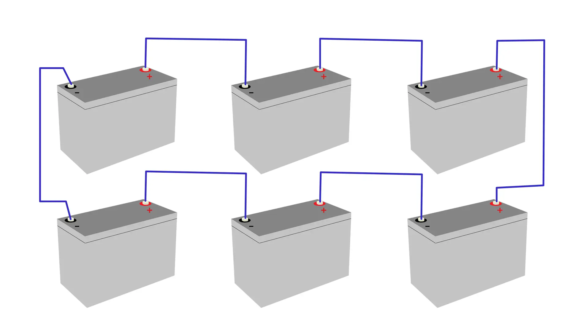
- Series and parallel connection of individual lifepo4 cells
The series and parallel connection method and number of individual cells also have a significant impact on internal short circuits. For example, the series connection can lead to the forced discharge of a specific individual lifepo4 cell, while the parallel connection can lead to the forced charging of a specific individual cell, both of which can result in excessive internal pressure and current in individual cells, leading to internal short circuits.
- Temperature control
A temperature control system is necessary to maintain the temperature of individual cells and the battery pack should work at a reasonable temperature range to ensure safety. Temperature monitoring technologies include air cooling, water cooling, and oil cooling.
In conclusion, understanding the causes of short circuits of LiFePO4 battery packs and implementing preventive measures, enhances the safety, associated with the batteries and mitigates potential risks. CM Batteries, as a professional LiFePO4 battery pack manufacturer, focuses on providing customized solutions with reliable quality and performance.


2 thoughts