Uninterruptible power supply (UPS) systems are critical in medical and industrial applications. However, many rechargeable battery-powered devices face power interruptions during battery replacement, leading to data loss or a short circuit. Hot-swap technology provides a solution by enabling direct battery replacement while the device remains operational. To meet the demand for rapid and safe power module replacement in high-power modular systems under load, this article first explores the fundamental concepts, working principles, advantages, and applications of hot-swap battery technology.
Why Is Hot-Swap Technology Critical in Modular Battery Systems?
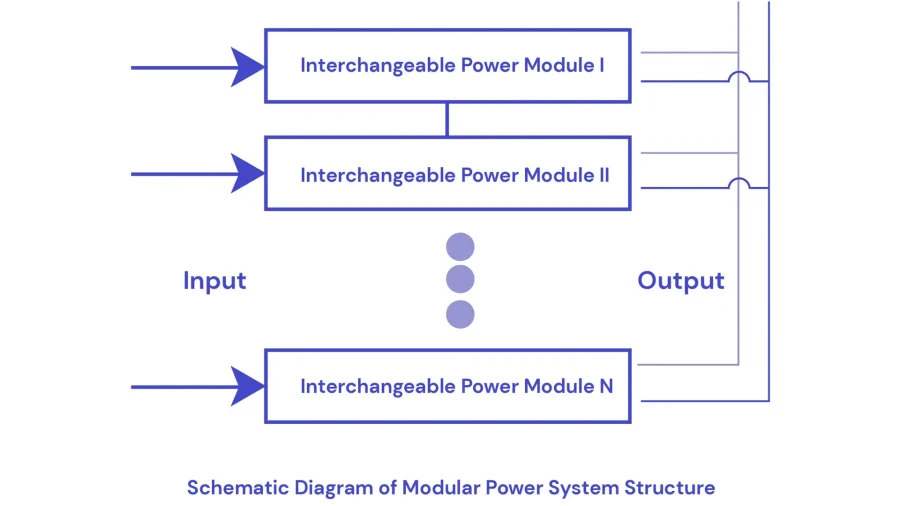
In high-power modular power systems (as shown in Figure 1), battery pack modules are typically connected in parallel to scale total output capacity. To maximize system reliability and allow rapid maintenance, the system must support live insertion and removal of replaceable modules without disrupting normal operation. This necessitates the integration of hot-swap capability into each module, which ensures seamless power delivery during maintenance or reconfiguration.
The absence of hot-swap capability prevents safe insertion or removal of battery pack modules during system operation. This limitation stems from the substantial inductors and capacitors present on the module’s BMS, which during live swapping can generate:
- Dangerous inrush currents exceeding component specifications
- Destructive voltage transients
- Potentially damaging electrostatic discharge (ESD) events
These phenomena pose significant risks of module damage and system-wide operational failure.
The absence of hot-swap capability prevents safe power module replacement during system operation. This limitation arises from both power and communication challenges: power path and signal integrity risks.
These combined effects may lead to module damage, system instability, or complete operational failure.
What is Hot Swapping Technology for Modular Batteries?
The core goal of a hot-swapping battery system is to enable the insertion or removal of modules or circuit boards without shutting down the device or disrupting system operation. This capability enhances system reliability, serviceability, redundancy, and disaster recovery.
In pack modular power systems, hot-swap technology ensures that faulty modules can be replaced while maintaining stable system voltage, allowing unaffected modules to continue operating normally.
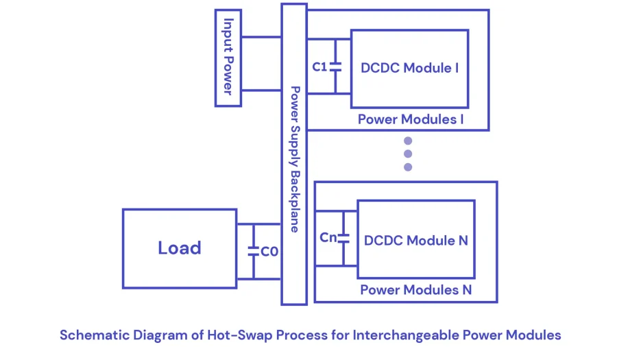
Figure 2 shows a simplified model of a pack modular system. The left side represents the system power supply and load, while the right side consists of multiple hot-swappable power modules. Here, C0 is the load’s input capacitor, and C1 to Cn are the input capacitors of the DC-DC converters in each module.
Assume all modules except Module N are connected to the backplane, and the system is operating stably. At this point, all capacitors except Cn are fully charged. When Module N is inserted into the backplane, a large inrush current flows as the system charges Cn, which can damage edge connectors, PCB traces, and capacitors.
Additionally, this high inrush current induces a voltage drop on the power bus, causing a temporary output voltage dip and system instability. If the current exceeds the system’s tolerance, the voltage may collapse, leading to a complete system failure.
Similarly, the sudden current surge can generate voltage fluctuations on the power module’s signal lines, potentially triggering communication errors or signal loss.
How Hot-Swap Works in Battery Modular Systems?
Hot-swapping encompasses both power hot-swap and signal hot-swap, each addressing critical challenges during module insertion and removal.
Power Hot-Swap: Mitigating Inrush Current
The primary goal of power hot-swap is to limit transient inrush current when a module is inserted into a live power bus. Without proper control, this surge current can cause voltage instability or hardware damage. A well-designed hot-swap circuit ensures that the current remains within safe limits, maintaining system integrity. Two common current-limiting methods are:
- PTC Thermistors (Positive Temperature Coefficient Resistors):
Self-regulate by increasing resistance as they heat up. Slow response and gradual degradation over time.
- MOSFET Switching:
Provides faster response and greater reliability for frequent operations. Preferred in high-performance systems due to its durability.
Signal Hot-Swap: Preventing Communication Errors
Signal hot-swap ensures safe disconnection of communication lines before power removal. Without it, transient voltages on signal lines can corrupt data or disrupt system communication. Proper implementation involves:
- Preemptive termination of active communication tasks.
- Isolation of signal lines to prevent voltage transients.
- Buffering circuits stabilize signal integrity during insertion and removal.
Hot-Swap Circuit Design for Safe Power Module
The hot-swap circuit consists of four main units: current sensing, control, switching, and short-pin signal detection.
- Current sensing uses a precision shunt resistor.
- Switching is implemented using an N-channel MOSFET.
- Control is managed by a comparator circuit.
- Short-pin detection employs a short pin and an optocoupler.
Show a simplified circuit diagram in Figure 3.
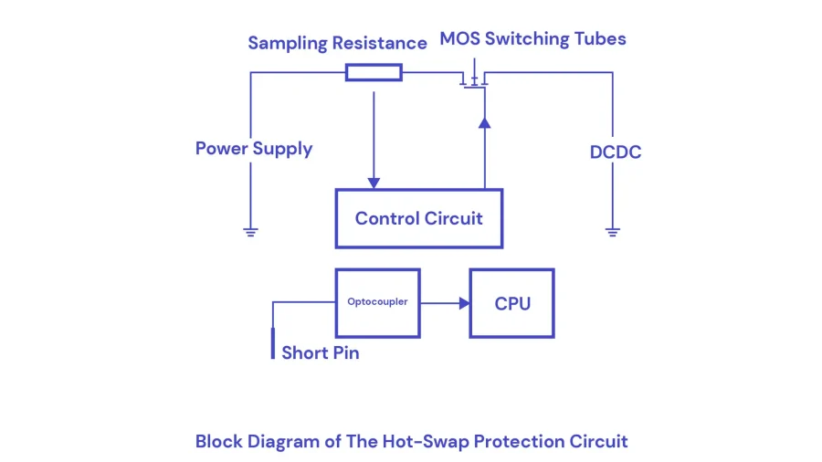
The MOSFET and shunt resistor are connected in series between the power supply and the load. The control unit monitors the current via the sensing resistor and the charge across a delay capacitor to regulate the MOSFET’s turn-on timing. This limits inrush current, ensuring system safety and stability, thereby enabling power hot-swap.
Additionally, the short-pin signal is used to detect module insertion or removal and to notify the CPU to terminate communication before power-off, thus implementing signal hot-swap.
Hot-Swap Application Circuit
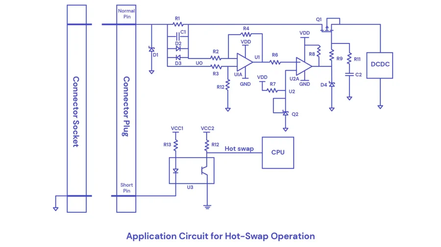
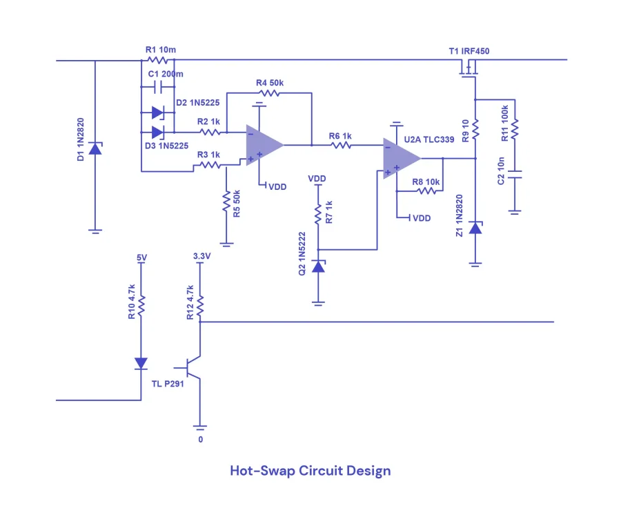
As shown in Figure 4, the short pin is approximately 3 mm shorter than the other pins. Key circuit components include:
- R1: Current sensing resistor
- C1: Delay capacitor
- D1–D3: Zener diodes
- R2–R5 and U1A: Differential amplifier
- R6, R8, and U1B: Voltage comparator
- R7 and Q2: Reference voltage circuit
- R9: High-frequency noise suppression
- R11 and C2: MOSFET Q1 gate delay
- R12, R13, U3, and the short pin: Signal detection circuit
When a replaceable module is inserted into the backplane:
- Primary pins connect first, supplying voltage. Current flows through R1, generating a sensing voltage U0, which charges C1.
- Once charge C1, the differential amplifier (U1A) amplifies U0 to get U1.
- The comparator (U1B) compares U1 with the reference voltage U2 (set by Q2 and R7):
- If U1 > U2, it indicates a high inrush current → comparator outputs low → MOSFET Q1 stays off.
- If U1 < U2, it indicates a safe current → comparator outputs high → C2 charges → Q1 gradually turns on, enabling smooth voltage rise to normal operation.
Signal Hot-Swap Operation
Signal hot-swap relies on the short pin, signal status, and software logic:
- On insertion:
- Primary pins connect first → short pin not connected → Hotswap signal = HIGH
- As short pin connects → Hotswap signal = LOW → CPU initializes communication
2. During operation:
- Hotswap signal remains LOW
3. On removal:
- Short pin disconnects first → Hotswap signal = HIGH → CPU stops communication and unloads drivers.
Hot-Swap Circuit Components
According to the power system requirements, each power module has a rated output voltage of 24V, a rated output current of 1.1A, and a maximum allowable current (IIM) of 5A. The TL431 voltage reference is used for Q3 to provide a stable 2.5V reference voltage (U2). The amplification ratio of the differential amplifier is set to R4/R2 = 50.
Key Component Selection
| Component | Model / Specification | Description |
| MOSFET | IRF540N (IR – International Rectifier) | N-channel MOSFET: 100V / 22A / 94W. Meets requirements: V > 24V, I > 5A, P > 28.8W |
| Optocoupler | TLP291 (Toshiba) | High-speed optocoupler with 10ms switching time. Used for fast signal transmission. |
| Current Sense Resistor | Custom | Used to detect inrush or load current and assist control logic. |
| Delay Capacitor | 10nF (C2) | Used to control timing delay for MOSFET gate drive, reducing inrush current. |
Supporting Components
| Component | Value / Model | Functionality |
| Operational Amplifier (U1) | OP07 (Precision, Low Offset) | Used for signal amplification with high precision. |
| Voltage Comparator (U2) | High-gain, wide bandwidth | Used to compare sensed voltage with reference (2.5V). |
| Zener Diodes (D1, D4) | 24V | Used for overvoltage protection and voltage clamping. |
Other Components Recommendations
- U1: OP07 precision operational amplifier (low offset voltage)
- U2: High-gain, wide-band voltage comparator
- Resistors:
– R2, R3 = 1kΩ
- R4, R5 = 50kΩ
- R7 = 100Ω (reference voltage divider)
- R6, R8 = 4.7kΩ (current-limiting resistors)
- R9 = 10Ω (noise suppression)
- R11 = 10kΩ (MOSFET gate resistor)
- Capacitor C2: 10nF (MOSFET gate delay control)
- Zener Diodes D1, D4: 24V for voltage clamping
Illustrated complete hot-swap circuit design in Figure 5.
Hot Swapping Batteries Applications
With the exponential growth of digital infrastructure and mission-critical applications, hot-swappable battery technology has become indispensable for maintaining continuous operations across multiple industries. This technology addresses the increasing power reliability demands of key application areas:
- Data centers and cloud computing platforms
- Telecommunications
- Financial transaction systems
- Military and defense electronics
- Medical emergency equipment
- Industrial automation systems
Operational Advantages
- Zero-Downtime Maintenance
- Enables real-time replacement of failed battery modules
- Supports capacity expansion without system shutdown
- Eliminates costly service interruptions in 24/7 operations
- Enhanced System Reliability
- Provides built-in power redundancy
- Maintains clean power delivery during module transitions
- Prevents voltage fluctuations that could disrupt sensitive electronics
Intelligent hot-swap controllers offer
- Real-time power monitoring
- Predictive failure analysis
- Automated load balancing
- Integrated circuit protection functions eliminate the need for external breakers
Technical Implementation Benefits
- Modular design flexibility for various battery chemistries (Li-ion, LiFePO4, etc.)
- Plug-and-play compatibility across power architectures
- Reduced total cost of ownership through
Performance Characteristics
- Seamless transition with <100μs power interruption
- Inrush current limited to <5% of rated capacity
- Support for parallel operation with automatic current sharing
- Standardized communication interfaces (CAN, PMBus, I2C)
By implementing hot-swappable battery solutions, organizations achieve unprecedented levels of system availability while significantly reducing operational risks associated with power maintenance and upgrades. The technology’s diagnostic capabilities further enable predictive maintenance strategies, optimizing both performance and cost-efficiency in modern power architectures.
In conclusion, as a professional manufacturer of lithium-ion battery packs, CM Batteries strives to provide customers with highly reliable power solutions. Not only do we focus on optimizing hot-swappable battery technology, but we can also customize a safe and efficient battery system for your specific application. If you are looking for a modular Li-ion battery pack solution that supports hot-swap technology, please feel free to contact us.


One thought